I was entrusted a TR-2025 and a TR-2080 from a antique shop/flea market. This is the TR-2080 – the Tandberg top-of-the-line model. Made in 1978 probably. It is essentially the same as the 2075 MkII. I have neither heard or worked on a 2075 or 2080. The restoration began in 2020.
This post became so long that I divided it in two parts. Pour yourself a cup or glass of something nice and enjoy the long and challenging restoration process of this TR-2080.
If you own a TR-2080 or plan to buy one – don’t be scared by the amount of work I put in, this was a total restoration of a unit in terrible condition. Normally you won’t have to do this much.
In part 1, I replace a shorted rectifier, locate a problem in the pre-pre amp, disassemble it (not as easy as it sounds), replace electrolytic capacitors, clean boards and internal connectors, replace lamps and FM pointer lamp, replace fried components, fix the antenna input and make some new small additional heatsinks.

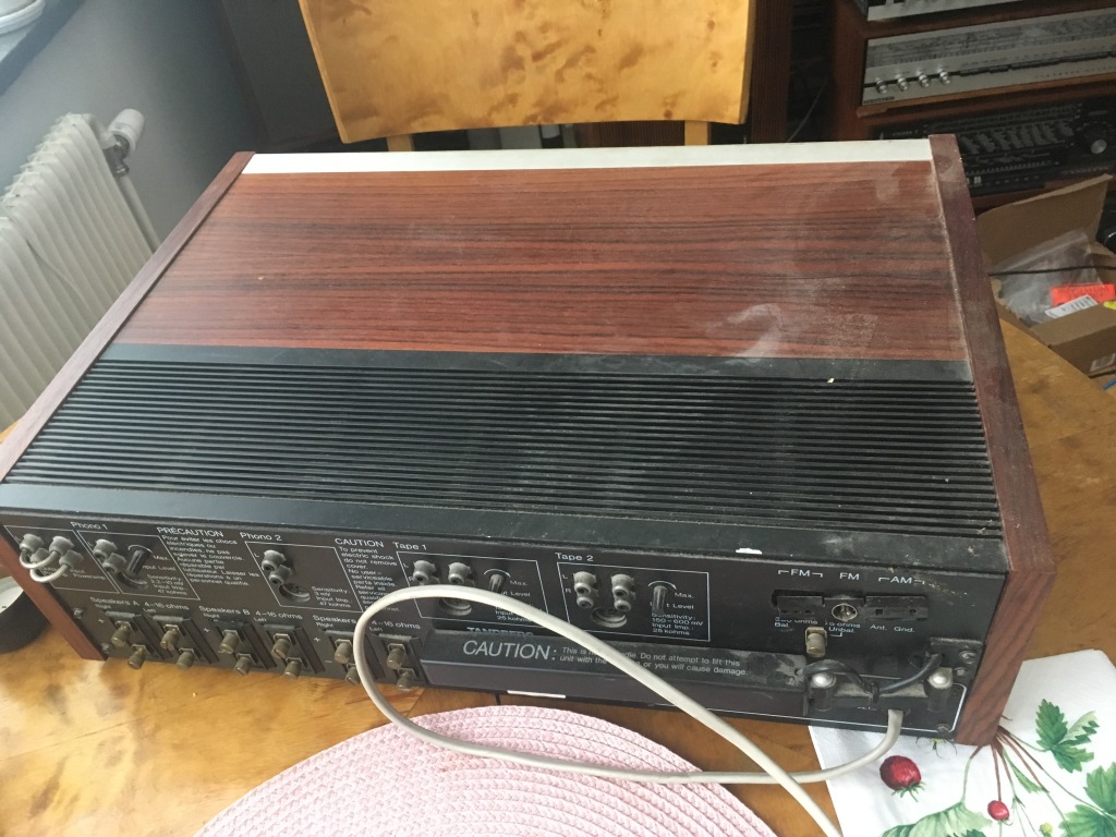


I tested it briefly with the DIY power limiter. All lamps are broken, not even the pointer lamp works. There was no sound, except from a very tiny, hardly hearable output. When checking the inside I found that the rectifier had a burned trace.
(Normally I inspect a unit inside before powering up. Not sure what steps I actually took here, forgot. Sometimes when the prior owner has tested it anyway I dare to do so too, because if something would burn it would probably already have. And I use the current limiter.)

I took out the rectifier and measured it. One diode shorted.


I repaired the trace. Then went to buy a new quad rectifier.


Testing it again after installing the new rectifier. It behaves erratically and there is almost no sound. It hums and pops. Measuring the rails there is power to the pre amp and power amp. Also, the radio works and makes a little bit of sound. Time to assemble my homemade schematics and get deeper into it.


With the schematics in hand I measured all the rails and found out that this amplifier has an input amp located on the input socket board and that this amp has no rail voltage. Tracing the voltage from where it is sent to the input board via the selector board, I found that it disappeared on the selector board. Inspecting it from below I found this burned trace.

I then fed this input amp +25V from the lab power supply. Connecting the input amp GND to chassis GND (it seems this point/cable is also signal GND), soldering off a jumper on the input amp board to prevent the normal +25V rail to be attached to the input amp (because there was voltage here, it was the GND line that had burned in the photo above). The input amp now had power from the lab supply.


It now produces sound on both channels, but it’s not proper sound really. Why had the input amp supply trace burned? I don’t know. Was afraid of a short in this section, which is why I wanted to use the lab supply to be able to limit current, but it seems to be ok. Perhaps someone dropped a screwdriver inside earlier, accidentally shorted it? Who knows. Someone had been in there before. The fuse on the transformer should be 3,15A T, it had been replaced with a 6,3A fuse. It is easy to misinterpret the text on the transformer. Maybe it had blown fuses when the rectifier failed.


I was beginning to take it apart completely to access the three different boards in the front. The selector board, which need a trace repair, is hard to work on if not taken out.
How to take off the tone control knobs (which have double knobs) – you need a hex screwdriver of 1,5mm.
The others are just to be pulled out gently.


Next I decided to temporarily fix the trace on the selektor board, just to test run it. Before taking it to pieces.

It now works, sort of, but not satisfactorily, it will need much more work. Injecting a signal (music) into the Tape inputs it plays with a weak sound and weaker on L channel. The radio sounds slightly better. It all lacks power however. I think it needs a complete recap. It will need 47 new electrolytic capacitors. It needs fixing of the power button (which I found inside, but the lever is broken off), It needs repair of the antenna connectors on the back. It needs some wood panel work. The power cable plug also looks like it has seen better days, almost like it got overheated. And it needs a massive cleaning, the horrendous grime on the outside. Also I would like to clean all connector pins and connectors inside, quite a lot of work, and of course the connectors and terminals on the back.
Maybe something else will show up, not unlikely at all. We’ll see..

It is dirty, the outside covered in dust and it’s like oily, when touched it leaves a oily residue on your fingers. Makes one wonder where this TR-2080 has been and what kind of life it had. The state of the capacitors also makes one wonder, as we will see below..

Let’s remove the boards. It wasn’t as difficult as I had feared. Screws, cables, removing the front parts, and levers of two lower buttons (they were losely attached to the switches, no violence required). There are several boards with cables running between them. High complexity. I took careful notes of all the cable positions before, and took photos.

There are lots of things to do, but lets start with the easy part, replacing capacitors.


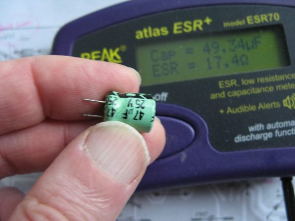
But what was the state of the caps? Was it necessary to replace ALL? In my so far not extensive experience the condition of the units I have worked on have differed vastly. This very TR-2080, I wonder what it has been through, poor thing, because there were many caps in bad shape. A few totally screwed, but others were just out of spec such that they would have worked but not performed well.
It makes me wonder if this TR-2080 has been running hot? Maybe someone placed in a tight space. Not a good idea, amps need air.


Pedantry can be fun. I thought that I should try to polish the cap legs before soldering. Have never seen anyone doing this or ever heard about it. But trying it I saw that there was some oxidation, or something, coming off. First polish with an old fibreglass pen (because it is old and a little worn it is not so abrasive), then clean with IPA. It shouldn’t hurt anyway, and maybe it will make the solder joint cleaner.
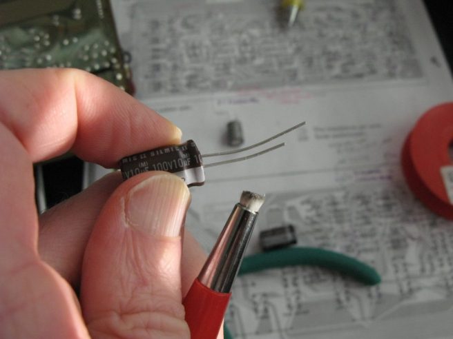

Solder joints should not look like this. These are original.


It’s sad to see the protective paint look like this. It’s from its earlier life. I am now careful to clean the boards on Tandberg gear because the paint dissolves so easily. It looks really bad. It means in some places there are old flux and oil from contact cleaner sprays left, but not sure how to clean the boards without damaging the surface. I have tried 3 or 4 diffent flux and board cleaners, some that were supposed to be ‘gentle’, but they are all solvent based and the result is like above. If you have a trick for how to clean and remove old flux and dirt without damaging the surface, let me know please.
PS, I have since found a spray paint for PCBs. It can be sprayed over a soldered board and can be soldered through. When applied it kind of improves the dissolved top coat above.
Recapping the FM and AM boards. Starting on the power amp board, but lacking some caps, like the 470uF/6V cap in the differential amplifier. So I will have to wait for the delivery from Mouser.

Ordered new caps on tuesday afternoon from Mouser and they arrive with FedEx express on wednesday morning. That is excellent service!
The 0,47uF caps go into the FM and AM board.

Continuing recap of the power amp. New 470uF/17V Nichicon Fine Gold caps goes there.
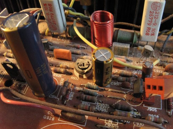

And now to the big power supply caps – four of them, two for each side of the power amp supply. Trying my best to not damage or burn the board, these were hard to get out, each having four legs. Only two of the legs on each are ‘active’ it seems.

I bought 4 fine Kemet 5600uF/100V caps. But they have those detestable solder lugs. How moronic isn’t that? I thought that they might fit, but no. They never fit and I am tired of drilling holes in boards, and even if drilling the fit is suspect with those tiny ‘ears’. Instead I decided for my favourite mod – capacitor banks consisting of radial, properly legged capacitors.
The Kemet’s won’t be used and I have to wait for 8 x Wurth 3300uF/63V capacitors from Mouser. Could have used higher V, but then they get bigger and the Wurths dont go higher than 63V. The originals were 63V. With a bank of multiple caps like this space is limited.
I really like the Wurth capacitors. German made (I think), low ESR, quality caps.

The internal cleaning is a “labour of love”, like I think Xraytonyb said on his youtube channel (recommended if you are a vintage hifi fan). It takes time and patience and lots of spray and IPA. My theory is that cleaning internal connectors is a good thing that possibly may improve performance, at least in a unit as dirty as this.


Trying to keep it clean, not to spill too much. The boards were dirty, some hardened grease on the surface, worse in some places. Cleaning it off without damaging the printed texts is a challenge. In some areas I cant make it totally clean without affecting the print so I leave some residue. But what to do. Not sure how to optimally do this, still experimenting.


I have got quite a few messages lately from readers of my humble blog. Thanks for reading! And thanks to Pawel from Poland, Anders and Gunnar from Sweden who contacted me during this week.
Now some not so fun parts. This 2080 is maybe the most troublesome Tandberg I have worked on so far. It is complex, parts are hard to reach. First to remove the whole power amp section. Should one have to remove everything in it to get out the power amp board? Can’t be. I found a way to cheat. The four screws that hold the middle section then the two screws that hold the power amp board. It can then be tricked out, not easy but can be done. It would probably have been better to dismantle the whole unit completely from the beginning. Who knew it would need this much work.


Traces of heat. Will look closer at this later.

Now to something as easy replacing lamps. Or so you would think! It was really annoyingly difficult.
The lamp board with the Soffitte 6x36mm lamps. How to access it? Well, you cant just remove the screws and pull it out, there is not enough space because of the radio boards. I got the recommendation to take off the front glass then the inner FM scale, so that the lamps, or some of them, could be accessed. But I couldnt get that FM scale off. It is stuck, maybe glued? Yes, I know about the screw below. Next option, unscrew the four screws at the edges behind the glass front. Then the front alu ramp can be gently pulled forward, which increases the distance between the radio boards and this ramp on which the lamp board also sit. Got to do it with utter care because the tuning thread runs here and you sure don’t want that to break or go off its wheel! And even when pulling this ramp forward there is hardly enough space to get the lamp board out. But you can by force and sheer willpower replace the lamps with the board bended and pulled. Of course the lamps will pop out in behind the FM scale, highly annoying. Luckily I didn’t break anything. But this surely is not the best engineering Tandberg has done. Or maybe just my unit. I am sure you can find an easier way.
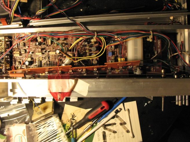

Now the little antenna socket board. Actually it is possible to get it out without unsoldering it inside the chassis. The cables have to be pulled or removed from their other ends, but no soldering needed, yet. Waiting for the replacement socket.
About 30 hours and 230 euro for parts spent so far. Still at lot to do..

Another thing, about capacitors. A reader remarked that all the caps were out of spec, or like had much less capacity than marked. Actually this is not the case, most caps on all (other) projects here in this blog were within spec. This very unit though – it has the highest failure rate of caps in any of the receivers I have worked on so far. A higher than normal percentage of them were ready for retirement.
Why is that? Maybe this unit took heavy use or was running hot. Or is it because this is quite a late model and we are already moving into modern times with the crappy quality of components that we have in modern throw-away electronics?
I conclude now after some more looking into it that it has been running hot. The age of the components is about the same as the TR-2025 and they were in better condition.
The antenna socket arrived. Thank you Thor!


Pointer lamps. I found on the TR-2025 that it is difficult to solder the lamp legs in and out without risking to melt the lugs on the plastic pointer. So I cut off the old lamp and left some leg and soldered in the new lamp on these, to thermally decouple the lugs so to say.


Next on the to do list was power transistor thermal paste replacement.
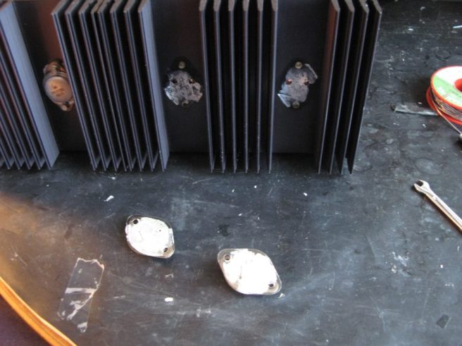

I had “modern” silicon pads, was going to use them. They need no thermal paste. But, not sure, I hesitated, want to stay original. So I ordered mica pads and have to wait for them. The old pads did not look fresh, one had a sort of blister.
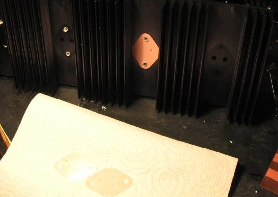
New pads arrived.
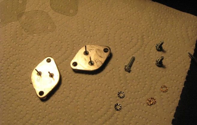


The thermal paste replacement went well. Oh, I measured the transistors while out. They seem ok although the Peak Atlas device gave some odd measurements.


Next I took out the rectifier and put in a new one, which I treated carefully before soldering in, to remove oxids and see if I can achieve better looking solder joints. It went decently well. Looks worse here than in reality.


Decided to replace the bias trim pots. Its easier to adjust with multiturn pots. Bourns pots, 220 ohm if I remember correctly. More than original but that won’t matter. Legs were too short, had to use cut off capacitor legs to make them longer.


If you have read this far you got to be really bored or really love vintage hifi and Tandberg, thanks for reading so far! Do stay. This is getting more and more interesting.
The next project was to make custom heat sinks. Maybe silly, but kind of fun. Some transistors in the power amp had been hot. The plan is to improve cooling. They may have been hot for some other reason, faulty components, bad ventilation around the unit, not sure. But anyway, lets do it.


There were two other transistors too that deserved real heatsinks. I had to manipulate them a bit to make them fit.


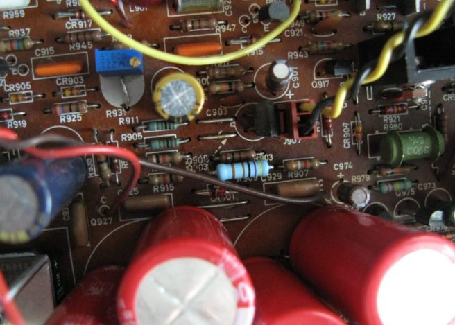
Because the traces of heat I also replaced R909 and CR901 and corresponding on the other channel. One of these resistors crumbled on removal, although they all measured ok they were maybe not in best health. New resistor of 4,7kOhm 1W 1 percent tolerance, and 15V 1,3W 2 percent tolerance zener diode, mounted a bit above the board, seen in the middle of the photo below, the resistor being a beautiful sky blue and the diode just below it.
To be continued in part 2. Don’t miss it!
In part 2, I replace the power supply filter caps with banks of several smaller caps, clean the chassis, polish radio scale glass, clean the relay, 3D print a new on/off switch part, trim FM, locate some faulty components, build new heatsinks, do a review at the end and tell you why the TR-2080 is a gentleman!
https://tandbergista.home.blog/tr-2080-part-2/
